
 Commercial alternative to evaluate: Motorola MOTOTRBO SLR5100 RepeaterRequest a quote →
Motorola DGR6175 Repeater discontinued
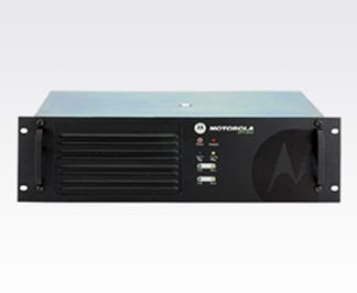
The Motorola DGR6175 is a MOTOTRBO repeater discontinued by the manufacturer. The page remains as a technical reference for existing operations, specialized support, and evaluation of current alternatives.
The equipment supports two simultaneous voice and data paths in digital TDMA, one RF channel, 100% continuous duty cycle at 40 W, and rack or wall mounting.
Discontinued
Manufacturer status.
2 TDMA paths
Voice and data.
100% at 40 W
Published full load.
14 kg
Published weight.

OVERVIEW
Technical reference for Motorola DGR6175
The DGR6175 serves installed MOTOTRBO networks with TDMA operation. As the model is discontinued, the commercial analysis should consider support for the existing installed base and current alternatives compatible with the need.
- Discontinued model, kept as technical reference
- Two simultaneous voice and data paths in TDMA
- Continuous duty at 40 W and rack or wall mounting
Digital TDMA
Two simultaneous paths
Voice and data on one RF channel.
• 12,5 or 25 kHz
• VHF or UHF
• Continuous duty
Discontinued model
Installed base
The page provides support and upgrade guidance.
• Technical identification
• System assessment
• Current alternatives
Motorola DGR6175: support for the installed base
The Motorola DGR6175 has been discontinued by the manufacturer. This page preserves the technical reference for maintenance of existing networks and evaluation of current alternatives.
Technical reference for Motorola DGR6175
The Motorola DGR6175 is a discontinued MOTOTRBO repeater. The official discontinued products page and the data sheet remain available as reference. For an installed network, this helps identify capacity, power, mounting, and equipment limits. For new deployments, the recommendation should compare current alternatives, without assuming stock or manufacturing continuity.
TDMA technology offers two simultaneous voice or data paths on a 12.5 kHz RF channel. The documentation also covers 25 kHz bandwidth according to operation and applicable regulation. The digital feature does not eliminate the need for coherent programming in terminals and system planning.
Published power and bands
Power depends on the band and version. The official data sheet presents VHF and UHF configurations with their own values, as well as 100% duty cycle at 40 W. The installed unit must be identified by model and band before any programming or replacement. One should not assume that one version covers all frequencies.
A higher-power repeater does not guarantee range by itself. Antenna, duplexer, cables, connectors, grounding, and installation position contribute to the result. In an aging fleet, cable degradation, oxidation, and antenna changes can affect coverage even when the repeater remains functional.
Rack or wall installation
The DGR6175 was designed for rack or wall mounting and has an integrated power supply. Published dimensions are 132.6 x 482.6 x 296.5 mm, with a weight of 14 kg. Operating temperature ranges from -30 °C to +60 °C. Installation must maintain ventilation, fastening, electrical protection, and technical access.
During a review, the team checks power, alarms, RF connectors, output power, receive sensitivity, and programming. Diagnosis also considers duplexer and transmission line, because a fault outside the repeater can produce similar symptoms.
Antennas, duplexers, cables, and external power supplies were not presented as generic accessories. They are design components and must have compatible band, power, connectors, and losses. The appearance of a part does not prove compatibility.
Support for installed base
ABC Mais Telecom can evaluate existing networks, review configuration, and guide migration. To start diagnosis, provide serial number, band, programmed power, radios in use, symptoms, installation location, and maintenance history. If there is a programming backup, it helps preserve groups and parameters during analysis.
A migration may require more than replacing the repeater. Licenses, controllers, terminals, antenna, power, and integration with other sites must be inventoried. The goal is to maintain operation and reduce risk, without claiming automatic compatibility with a current alternative.
Technical checklist for specifying the Motorola DGR6175
Specifying the Motorola DGR6175 begins with identifying the exact version. The page does not combine features from different versions. Published capacity is one RF channel and two simultaneous TDMA paths, and RF output is up to 40 W on a 100% duty cycle, observing each version’s own power rating. The project must relate these data to the authorized band, number of groups and radios already participating in the operation.
1. Confirm band and version before programming
For the Motorola DGR6175, the VHF or UHF version identified on the installed unit must be confirmed. Frequency is not chosen solely by user preference. It must comply with regulation, license when applicable, and compatibility with portables, mobiles, antenna, and duplexer. The complete unit code helps avoid configuration based on a different variant.
2. Measure the installation point
The location for the Motorola DGR6175 must be inspected before mounting. Available height, cable routing, grounding, ventilation, maintenance access, and distance to the antenna influence the result. The equipment measures 132.6 x 482.6 x 296.5 mm and weighs 14 kg. These measurements help check rack, wall, cabinet, and service space without improvisation.
3. Size antenna and duplexer
Antenna and duplexer are not universal accessories for the Motorola DGR6175. Band, transmit-receive separation, power, and losses must be compatible. Duplexer tuning must be measured with appropriate instruments. A visually similar part may operate in another band and impair coverage, reception, or transmitter protection.
4. Calculate transmission line losses
Cable length and type, connectors, joints and surge protection affect the power reaching the antenna. The published output of up to 40 W at a 100% duty cycle, observing the power rating of each version, does not automatically equal radiated power. For the Motorola DGR6175, the design records these losses and checks the standing-wave ratio before concluding that a coverage problem comes from the repeater.
5. Prepare power and contingency
The Motorola DGR6175 is powered by an integrated power supply, checked during diagnostics. The power supply, circuit breakers, cables and any backup battery must be sized for actual consumption and the desired backup duration. An electrical input does not establish that any power supply is suitable. Polarity, voltage, current and protection must be checked.
6. Plan programming and groups
Programming of the Motorola DGR6175 must be coherent with all radios in the system. Frequencies, channel bandwidth, color code, groups, lists, and analog or digital parameters are documented before changes. A validated backup reduces risk of configuration loss. Changes are tested in a controlled manner because a repeater affects many users at once.
7. Validate network features
For the Motorola DGR6175, MOTOTRBO programming compatible with the installed fleet must be considered. An Ethernet connector or a mention of IP does not guarantee ready-to-use interconnection. The version, licenses, topology, addressing, security and network availability must be confirmed. Conventional communication must also remain documented for diagnosis.
8. Commission with measurements
After installation, the Motorola DGR6175 undergoes verification of power, frequency, modulation, reception, alarms, and operation with real terminals. The radiating system is also measured. Voice tests are performed at representative points in the environment. The report must separate measured facts from estimates, avoiding turning a test condition into a general range promise.
9. Document preventive maintenance
The routine for the Motorola DGR6175 may include inspection of power supply, ventilation, connectors, grounding, cables, alarms, and programming parameters. Failure history and infrastructure changes help find root cause. When coverage changes, investigation considers antenna and transmission line before concluding that the RF module needs replacement.
10. Respect the model’s life cycle
Motorola DGR6175 is an officially discontinued model, retained on this page as a support and migration reference. There is no promise of stock, future manufacture or a warranty beyond that published by the manufacturer. As a discontinued model, the focus is the installed fleet and migration.
11. Separate proven components from generic items
Infrastructure components remain within the technical scope, but are specified by band, power and installation, not by appearance or image reuse.
12. Information for a responsible quote
To evaluate the Motorola DGR6175, send city, band, frequencies, number of users, existing radios, area, obstacles, installation point, and network need. Photos of infrastructure and programming backups also help. ABC Mais Telecom uses this data to guide study, deployment, programming, and specialized technical service without forcing a solution before diagnosis.
Technical specifications
Data from the official Motorola Solutions Brazil page and the official DGR6175 data sheet. Power and frequency are presented per band.
1 RF channel
Two TDMA paths.
Power per band
VHF and UHF distinct.
100% at 40 W
Full load.
Integrated power supply
Published power supply.
Detailed data sheet
| Status | Discontinued by the manufacturer |
| Technology | MOTOTRBO TDMA digital |
| RF channel | 1 |
| TDMA paths | 2 simultaneous paths for voice and data |
| VHF | 136 to 174 MHz; 1 to 25 W or 25 to 45 W |
| UHF band I | 403 to 470 MHz; 1 to 25 W or 25 to 40 W |
| UHF band II | 450 to 527 MHz; 1 to 40 W or 25 to 40 W |
| UHF above 512 MHz | 1 to 25 W |
| Duty cycle | 100%; continuous operation at 40 W |
| Channel spacing | 12.5 or 25 kHz |
| Power supply | Integrated power supply |
| ProtocolETSI TS 102 361-1 | |
| Vocoder | AMBE++ |
| Mounting | Rack or wall |
| Operating temperature | -30 °C to +60 °C |
| Dimensions | 132,6 × 482,6 × 296,5 mm |
| Weight | 14 kg |
Features explained
Suitability for the infrastructure must be verified in the technical design.
Digital TDMA
Digital TDMA mode provides two simultaneous voice and data paths using one RF channel. Performance depends on network configuration and the radiating system.
Bands and power
In VHF from 136 to 174 MHz, there are versions from 1 to 25 W or 25 to 45 W. In UHF from 403 to 470 MHz, there are versions from 1 to 25 W or 25 to 40 W. In UHF from 450 to 527 MHz, there are versions from 1 to 40 W or 25 to 40 W, with a limit of 1 to 25 W above 512 MHz.
Mounting and power supply
The manufacturer specifies rack or wall mounting and an integrated power supply. The height is 132.6 mm.
Protocol and channel spacing
The published protocol is ETSI-TS102 361-1, with AMBE++ vocoder and channel spacing of 12.5 or 25 kHz.
Dimensions and environment
Dimensions are 132.6 × 482.6 × 296.5 mm and weight is 14 kg. The published operating temperature ranges from -30 °C to +60 °C.
Installed base and alternatives
Product discontinued by the manufacturer. Contact ABC Mais Telecom to assess support for the installed base or current alternatives.
Technical consultation
If there are questions about networks, accessories, or intended use, provide the context so the sales team can evaluate the appropriate configuration.
Manufacturer source
Product discontinued by the manufacturer. Contact ABC Mais Telecom to assess support for the installed base or current alternatives.
When to request an evaluation
The page serves to identify the installed DGR6175, document its configuration, and guide an analysis of maintenance, continuity, or technological upgrade.
Manufacturer source
Product discontinued by the manufacturer. Contact ABC Mais Telecom to assess support for the installed base or current alternatives.
Installed base and migration of the Motorola DGR6175


As the DGR6175 is discontinued, the purpose of this page is to guide technical support and upgrade planning.
When to review an installed DGR6175
Coverage failures, alarms, overheating, loss of power or programming changes warrant diagnosis. Testing must distinguish repeater faults from antenna, duplexer and cable problems.
Migration planning
A current alternative, such as MOTOTRBO repeaters SLR5100 and SLR8000, must be compared by band, power, modes, licenses, interfaces and network compatibility. Replacement must not be promised without a system inventory.
Installed-fleet documentation
A programming backup, radio list, frequencies, groups and maintenance records reduce risk during support or upgrades.
Technical consultation
ABC Mais Telecom can assess existing equipment and provide guidance on alternatives, without claiming future stock for a discontinued model.
System components
DGR6175 wall mount kit
: PMLE4476
Equipment: Motorola DGR6175 Repeater
PMLE4476 is a mechanical mounting kit, not part of the RF chain.
As the DGR6175 is a discontinued platform, kit availability and integrity must be confirmed. Mounting must preserve the ventilation and connection access specified for the repeater.
- Function:
- wall mount
- Model:
- DGR6175
- Documentation: catalog
- official legacy reference
Request a quote
Fill in the fields to receive a technical quote, with price on request and guidance on the usage scenario.
Loading accessories…
Response by email and WhatsApp. No obligation · price on request. We also rent: in rentals, Anatel frequency licensing is already included by ABC Mais Telecom.
Frequently asked questions
Has the Motorola DGR6175 been discontinued?
How many TDMA paths does the DGR6175 offer?
TDMA digital operation offers two simultaneous voice or data paths on one RF channel.
What is the published duty cycle?
The manufacturer publishes a 100% duty cycle at 40 W. Power and range depend on the version.
Can the DGR6175 be rack mounted?
Installation can be done on a rack or wall, with integrated power supply.
How to specify components for the DGR6175?
Antenna, duplexer, cables, connectors and electrical protection must be specified according to frequency band, power, losses and installation conditions. The appearance of a part does not prove compatibility.
How to evaluate a current alternative?
For new deployments, the current alternative should be evaluated based on the existing network.